> For the complete documentation index, see [llms.txt](https://help.movin3d.com/llms.txt). Markdown versions of documentation pages are available by appending `.md` to page URLs; this page is available as [Markdown](https://help.movin3d.com/movin-tracin-stage/setup/calibration.md).

# Stage 1 · Calibration

Calibration aligns the sensors into one shared 3D scene. You perform it by moving a calibration wand — a spherical target mounted on a rod — throughout the stage while the sensors detect it. The reference sensor — usually one mounted high overhead and aimed down — defines the coordinate frame to which all other sensors are aligned.

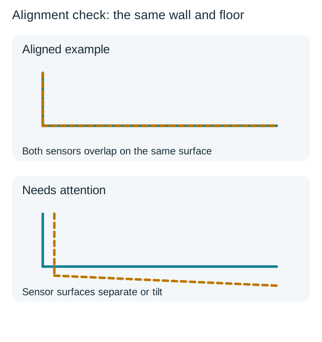
Perform calibration at initial installation, after a sensor is moved or replaced, or when the scene appears misaligned (for example, doubled walls or an offset floor). Before you begin, keep the wand within reach, make sure the entire stage is clear and accessible, and confirm that every sensor is powered, connected, and PTP-synced.

Before opening the six-step wizard, complete the following two screens.

## Before the wizard

### Calibration guide card

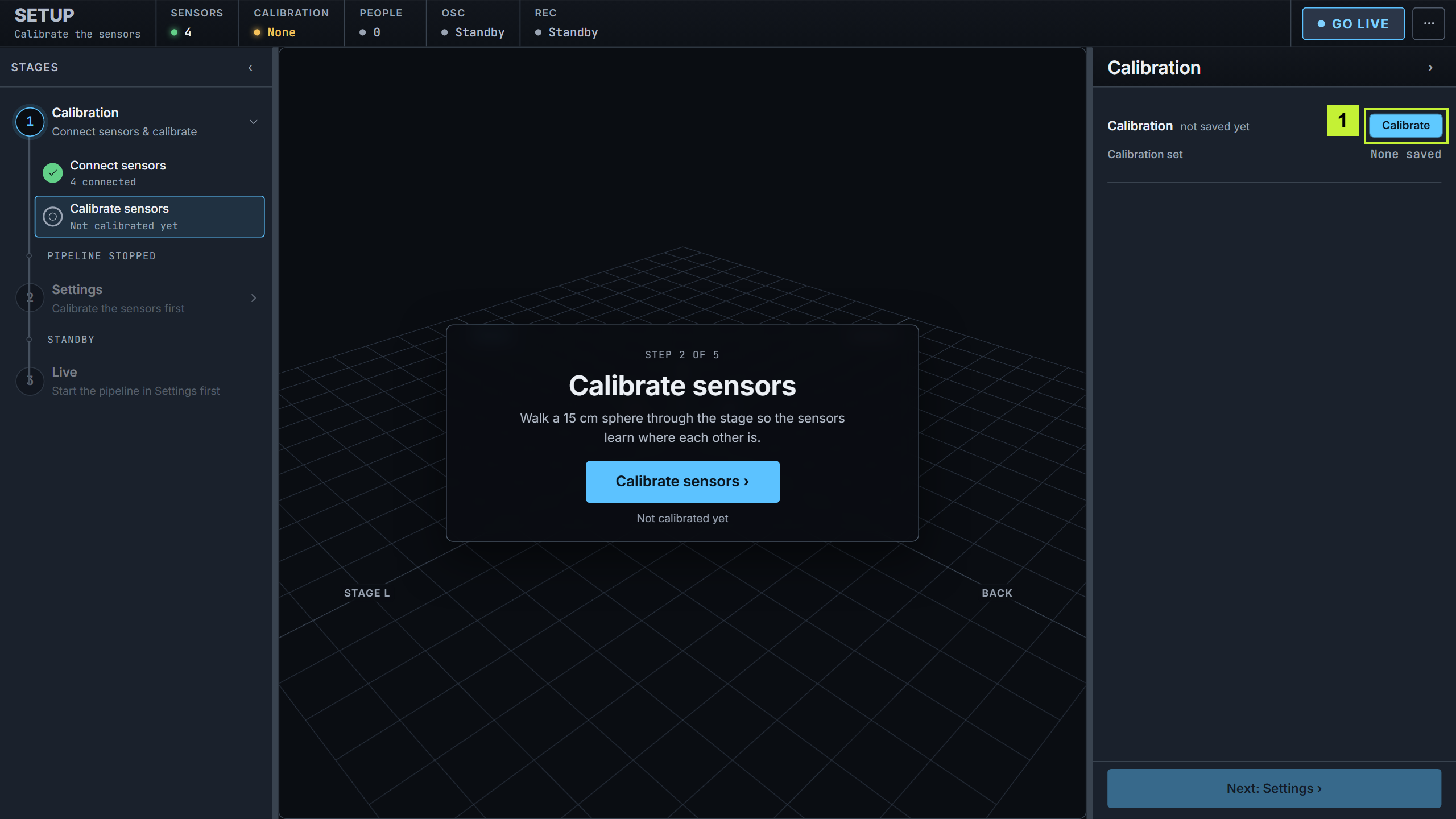
<figure><img src="/files/HaSxZYM3MLQGlVJVBttz" alt="Calibration guide card"><figcaption><p>The Stage 1 landing card.</p></figcaption></figure>

1. **What this stage does** — connect the sensors, then calibrate them. The pipeline starts from Live Settings, once calibration is done.
2. **Two paths** — **Next: Connect sensors →** to begin, or **Skip to Live Settings →** if a valid calibration is already loaded.

### Connect sensors

<figure><img src="/files/jUYRuvXJDMCwkszcqHe0" alt="Connect sensors screen"><figcaption><p>Select the sensors and the reference before the wizard opens.</p></figcaption></figure>

1. **Sensors** — every detected sensor. Select the reference sensor used to align all other sensors — usually a ceiling-mounted LiDAR aimed down over the stage. A **REFERENCE** badge identifies the selected sensor. **Refresh sensors** re-scans if one is missing.
2. **Where is the reference mounted?** — **Ceiling** (aimed downward) or **Floor** (upright). This only orients the preview; the saved calibration is unaffected.
3. **Timecode / LTC** — the incoming Linear Timecode (LTC), shown for reference. It does not affect calibration.
4. **Next: Calibrate sensors →** — opens the wizard.

{% hint style="info" %}
Calibration is locked while the pipeline is running. Selecting it prompts you to stop the pipeline first, which unlocks the wizard. The show stops broadcasting until you go live again.
{% endhint %}

## Step 1 · Setup

*Check the sensor status and select the wand type. The stream starts automatically.*

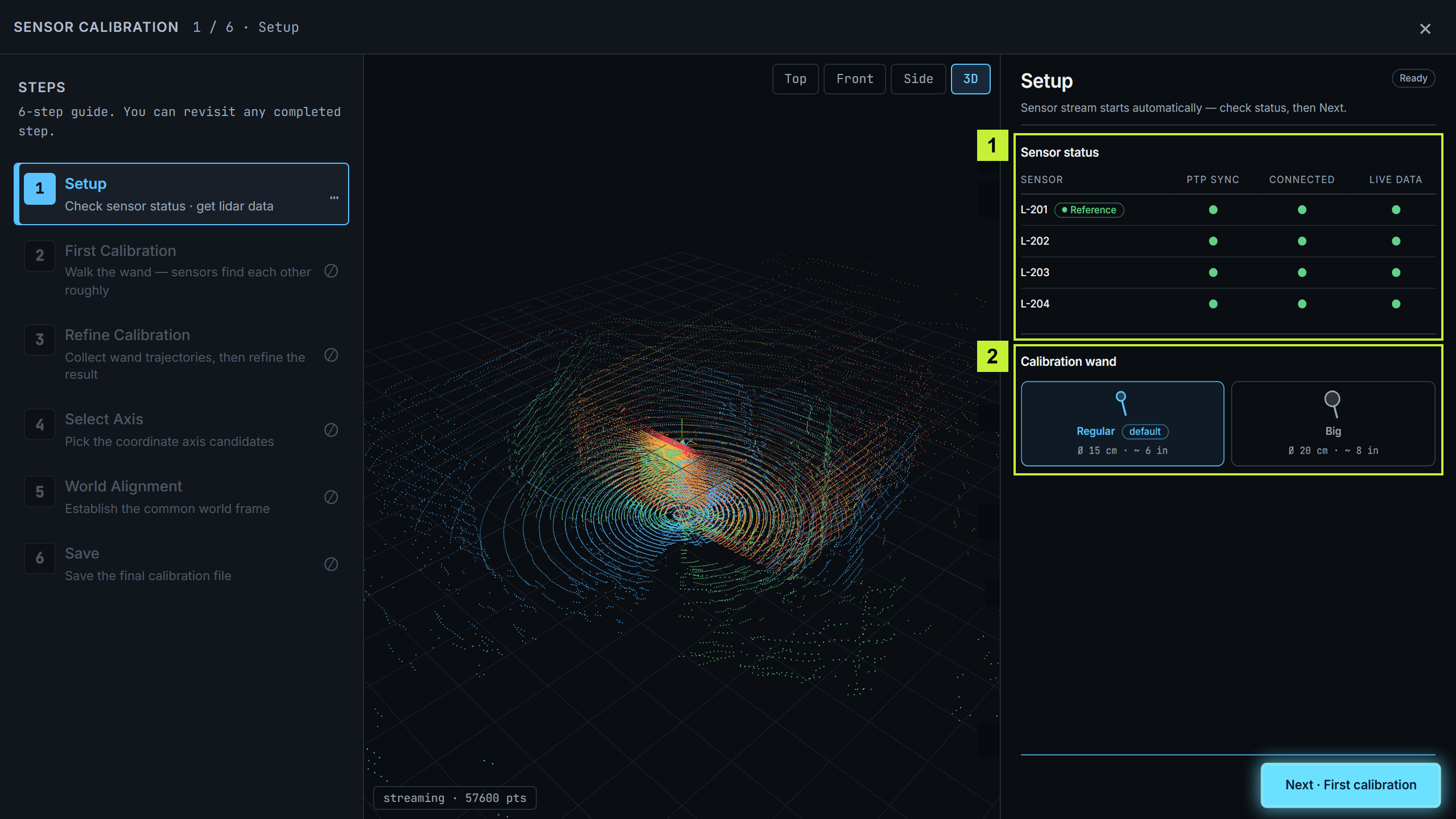
<figure><img src="/files/MPAKAlPxXbw6vgs1qCXb" alt="Step 1 Setup — sensor status and calibration wand"><figcaption><p>All four sensors are PTP-synced, connected, and streaming.</p></figcaption></figure>

Confirm each sensor shows three green indicators — **PTP synced**, **Connected**, and **Live data** — then select the wand type you are holding: **Regular** (15 cm diameter) or **Big** (20 cm diameter). The stream starts automatically; if a sensor does not connect or begin streaming, select **Reconnect sensors**. When every indicator is green, select **Next · First calibration**.

{% hint style="warning" %}
PTP synchronization is required when two or more sensors are used. Without a shared clock, the alignment does not converge. A single sensor used for testing does not require it.
{% endhint %}

## Step 2 · First Calibration

*Move the wand throughout the stage to create an initial alignment.*

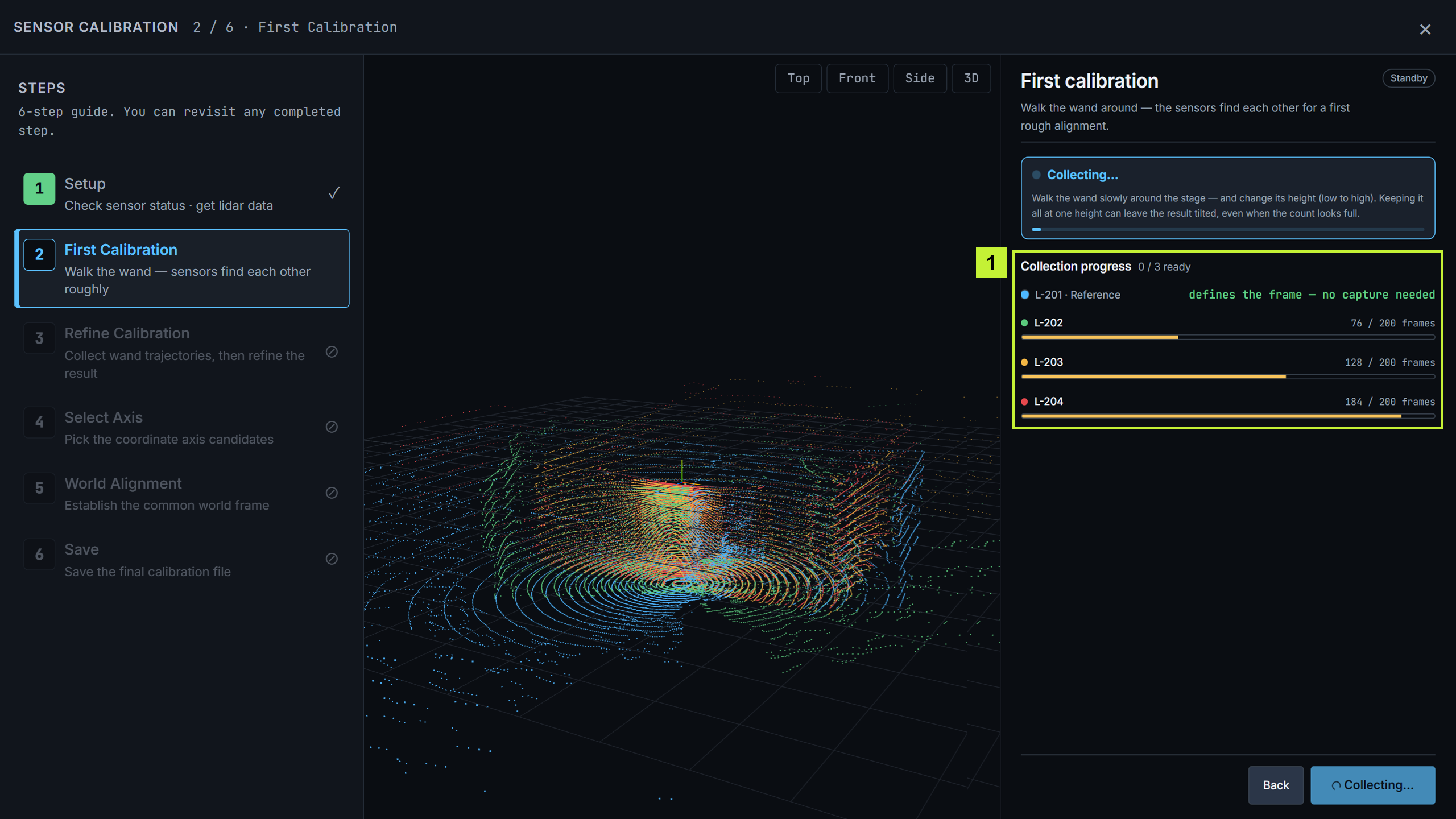
<figure><img src="/files/aIyc48gsoEIlKmWYjwf9" alt="Step 2 First Calibration — collecting"><figcaption><p>The reference defines the frame; the other sensors fill in as the wand enters their view.</p></figcaption></figure>

1. Select **Start collection**, then move the wand slowly to several positions across the stage at roughly the same comfortable height. Step 2 only creates the initial alignment; you will cover different heights in Step 3.
2. Collection stops automatically when every non-reference sensor has at least 200 tracked frames, all sensors are ready, and the overall result is **Good**. Select **Stop collection** only when you need to finish early.
3. **Collection progress** — the reference reads *defines the frame — no capture needed*; the progress indicators for the other sensors fill as the wand enters their fields of view.

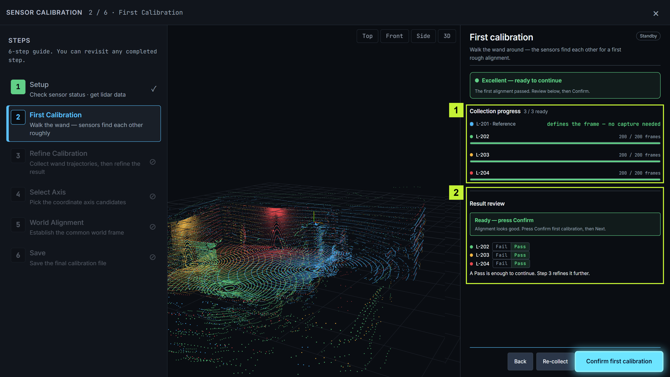
<figure><img src="/files/3TWrIbA4PoKtzNX9P0FT" alt="Step 2 — all sensors ready"><figcaption><p>Every sensor has collected enough frames, and the result review shows Good.</p></figcaption></figure>

1. **All sensors ready** — every sensor has reached the minimum confirmation threshold. Keep moving the wand until collection stops automatically.
2. **Collection progress** — a sensor can read e.g. `50 / 50 frames · ready` before the 200-frame automatic-stop threshold is reached.
3. **Result review** — a per-sensor quality check; **Good** means the alignment looks right.
4. **Confirm first calibration** — save the initial result and continue to Refine Calibration.

## Step 3 · Refine Calibration

*Move the wand throughout the capture volume to collect trajectory data, then refine the alignment.*

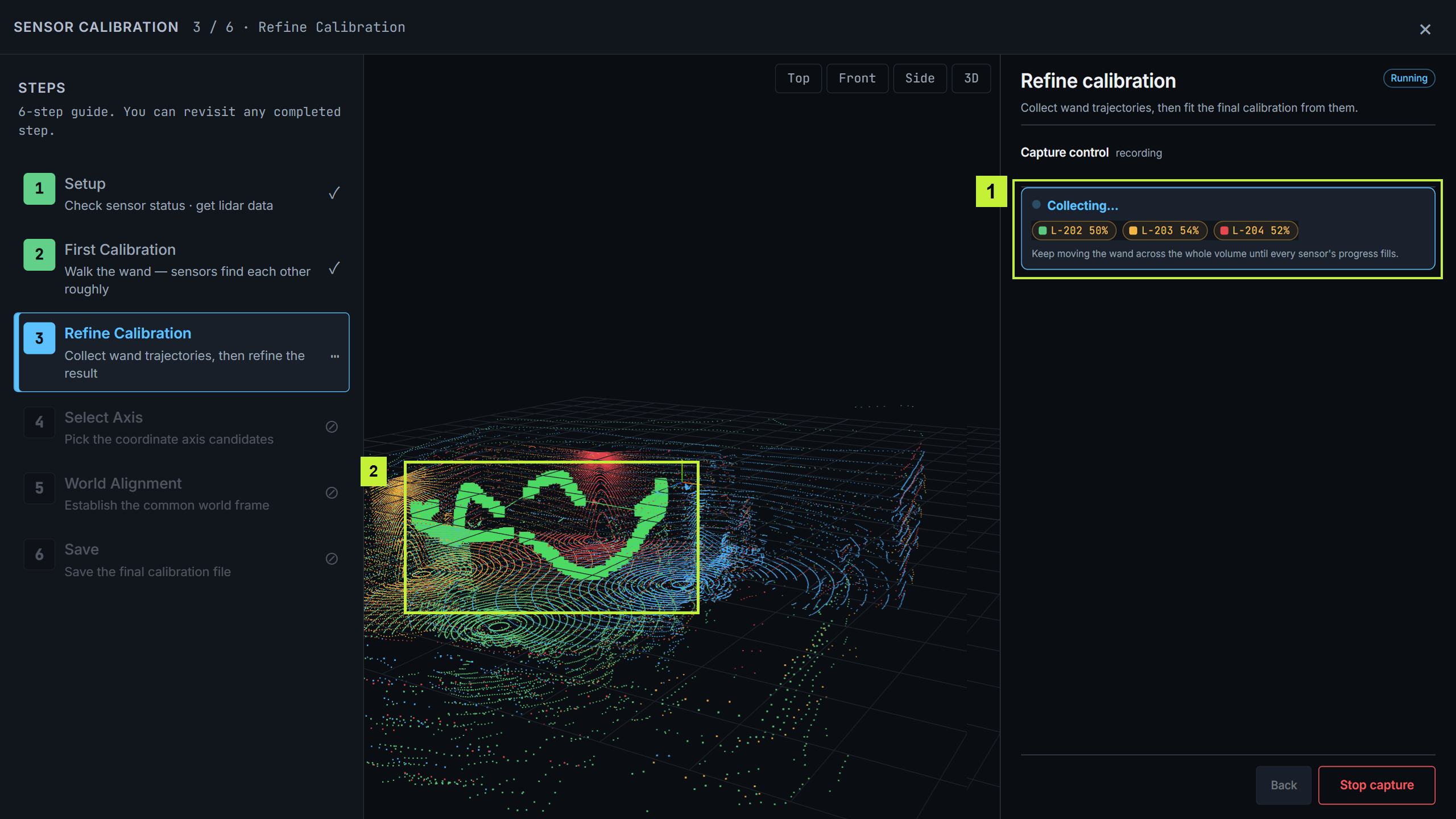
<figure><img src="/files/3zVOBm7RLGMixi27iuII" alt="Step 3 Refine — collecting trajectories"><figcaption><p>The green loops show the captured path; the per-sensor percentages show progress toward 300 new samples.</p></figcaption></figure>

1. Select **Start capture**, then move the wand across the full capture volume, raising and lowering it as you go. Aim to cover at least about 0.8 m of height variation. Each sensor's percentage (e.g. `L-202 50%`) tracks progress toward 300 new samples; it is not a spatial-coverage score. Spatial coverage is checked separately, so spread the path throughout the volume as well as completing each percentage.
2. **Capture summary** — accepted and skipped trajectories, counted live.
3. **Stop capture** — select it once sufficient coverage has been collected.
4. In the viewport, the **green loops** are the path you have covered.

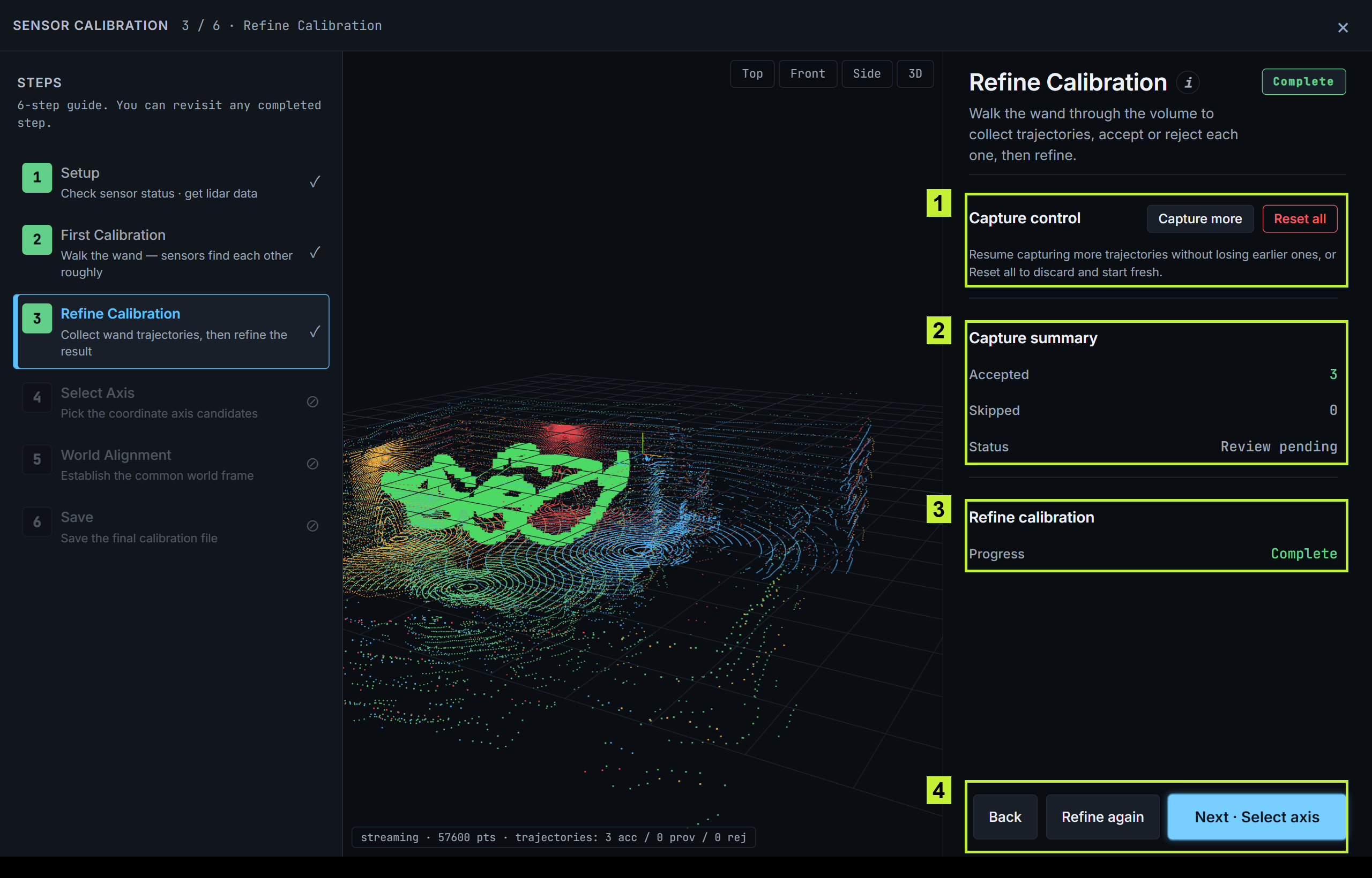
<figure><img src="/files/Jjv3pWSjYekukbSrLy6s" alt="Step 3 complete — Refine Complete"><figcaption><p>Trajectories accepted and the Refine calibration status shows Complete.</p></figcaption></figure>

1. **Capture control** — **Capture more** adds trajectories without losing earlier ones; **Reset all** starts fresh.
2. **Capture summary** — the accepted trajectories.
3. **Refine calibration** — the optimization has run and shows **Complete**.
4. **Next · Select axis** — continue.

## Step 4 · Select Axis

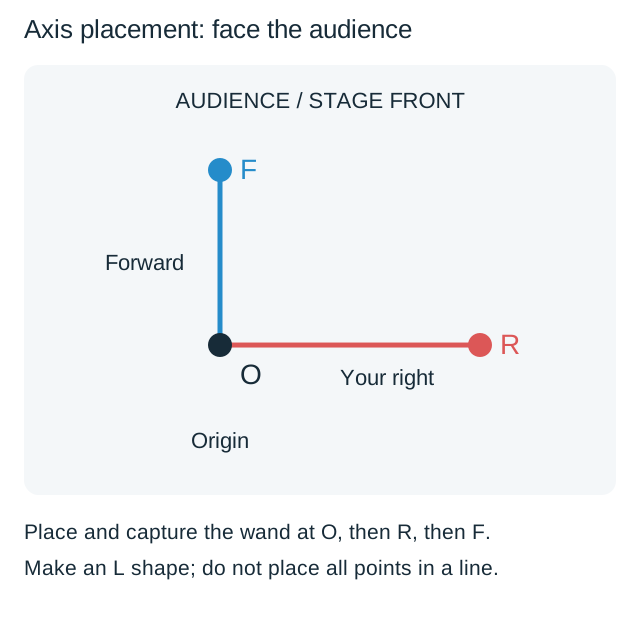
*Define the origin, right, and forward directions, in that order. Set them while facing the stage, so the frame matches the stage.*

<figure><img src="/files/XPdES3ZHrtg3aW2tEboO" alt="Step 4 Select Axis — Origin"><figcaption><p>Place the wand at the center, step clear, then confirm that it is placed to start the timed capture.</p></figcaption></figure>

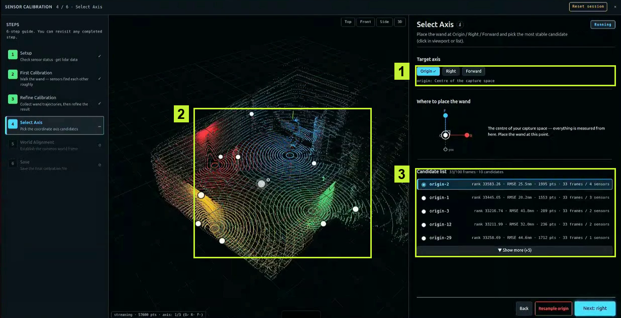
1. **Target axis** — starts on **Origin**.
2. **Where to place the wand** — the diagram shows each spot: **O** (the stage center), **R** (to your right), and **F** (the forward direction you face).
3. Select **Start origin capture**, place the wand at **O**, step clear, then select **Placed — start capture** in the placement dialog.
4. Capture ends automatically after 100 synchronized frames or about 5 seconds, whichever comes first. The candidate list then fills with scored positions.

<figure><img src="/files/hnUALc4QCKjoj1WOyL07" alt="Step 4 — candidates in the viewport"><figcaption><p>Each candidate appears as a marker in the 3D view.</p></figcaption></figure>

Each candidate appears as a marker in the 3D view. The highest-scoring candidate is preselected; verify that it matches where you actually placed the wand, or select another. (RMSE reflects how consistently the wand was detected — lower is generally better — but always pick the marker at the wand's real position.)

<figure><img src="/files/SwLT6AdOGBdL1hDBsFdN" alt="Step 4 — Right axis"><figcaption><p>The white O marker shows the confirmed origin; now place the wand to your right.</p></figcaption></figure>

1. **Target axis** switches to **Right**.
2. The diagram now points to the **R** spot — place the wand there and step clear.
3. Select **Start right capture**, confirm **Placed — start capture**, then review and confirm the candidate as you did for the origin.

<figure><img src="/files/OTkRVCdTxMxbNfWo9Wlq" alt="Step 4 — all three axes confirmed"><figcaption><p>With all three axes confirmed, the O, R, and forward markers define the world frame.</p></figcaption></figure>

Repeat once more with **Start forward capture**. When all three axes show a check mark, select **Next · World alignment**.

## Step 5 · World Alignment

*Finalize the shared coordinate frame, adjust the floor, and confirm.*

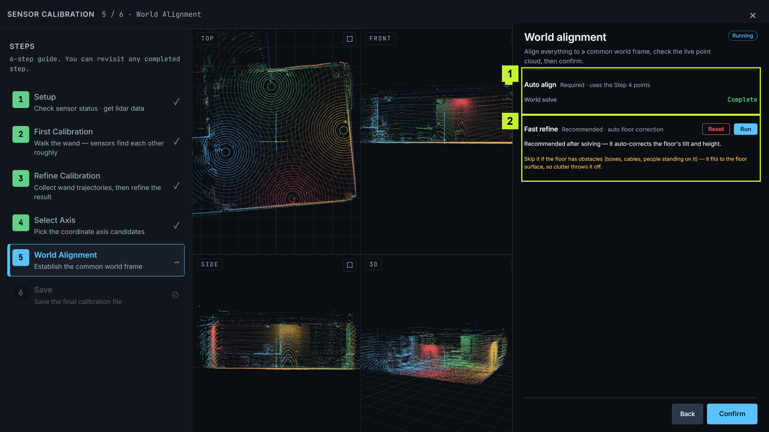
<figure><img src="/files/DWdhlXnPhyuDaLb0icyj" alt="Step 5 World Alignment — Top, Front, Side, and 3D views"><figcaption><p>The viewport splits into Top, Front, Side, and 3D views so you can verify the result from every angle.</p></figcaption></figure>

1. **Auto align** (required) — **World solve** starts automatically when you enter Step 5, computes the common frame from your Step 4 points, and shows **Complete** when done. If it fails or you need to calculate it again, select **Run World Solve**.
2. **Fast Refine → Run** (recommended) — auto-corrects the floor's tilt and height. Skip it if the floor has objects on it (boxes, cables, or people), because it estimates the floor plane from the visible floor points.
3. **Manual fine-tune** — rarely needed; use it only if the floor is still tilted or offset after Fast Refine.
4. **Confirm** — verify in the **Top / Front / Side / 3D** views, then confirm.

## Step 6 · Save

*Save the calibration so it can be used when the pipeline starts.*

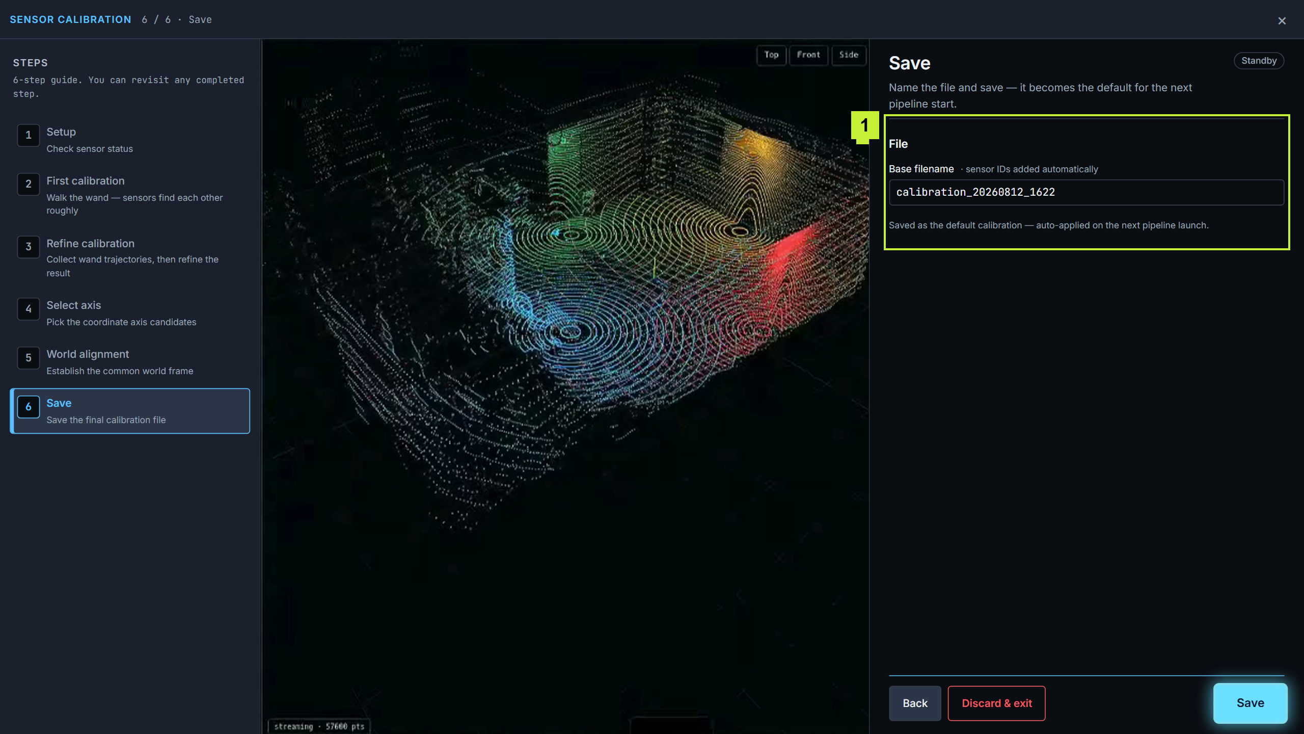
<figure><img src="/files/8vtCBfIAtErb7McL5Qh8" alt="Step 6 Save — timestamped filename"><figcaption><p>A timestamped filename is prefilled; saving it sets it as the default calibration.</p></figcaption></figure>

A timestamped **base filename** is prefilled, with sensor IDs added automatically — change it if necessary. Select **Save**, and the calibration becomes the default, applied automatically the next time the pipeline starts. **Discard & exit** leaves without saving and clears all in-progress wizard data, including trajectories, selected axes, manual alignment, and refinement results.

## Next

Continue to [Stage 2 · Live Settings](/movin-tracin-stage/setup/live-settings.md). Once the pipeline starts, calibration is locked until you stop the pipeline and reopen the wizard.


---

# Agent Instructions
This documentation is published with GitBook. GitBook is the documentation platform designed so that both humans and AI agents can read, navigate, and reason over technical content effectively. Learn more at gitbook.com.

## Querying This Documentation
If you need additional information that is not directly available in this page, you can query the documentation dynamically by asking a question.

Perform an HTTP GET request on the current page URL with the `ask` query parameter, and the optional `goal` query parameter:

```
GET https://help.movin3d.com/movin-tracin-stage/setup/calibration.md?ask=<question>&goal=<endgoal>
```

`ask` is the immediate question: it should be specific, self-contained, and written in natural language.
`goal` is optional and describes the broader end goal you are ultimately trying to accomplish on behalf of the user. GitBook uses it to tailor the answer towards what is most useful for that goal.

The response will contain a direct answer to the question and relevant excerpts and sources from the documentation.

Use this mechanism when the answer is not explicitly present in the current page, you need clarification or additional context, or you want to retrieve related documentation sections.