> For the complete documentation index, see [llms.txt](https://help.movin3d.com/llms.txt). Markdown versions of documentation pages are available by appending `.md` to page URLs; this page is available as [Markdown](https://help.movin3d.com/movin-tracin-stage/install-the-hardware/whats-included.md).
# What you need
What ships with MOVIN TRACIN Stage — four LiDAR sensors, the server, the PoE switch, and the calibration wand — and the stands, clamps, and cables you supply.
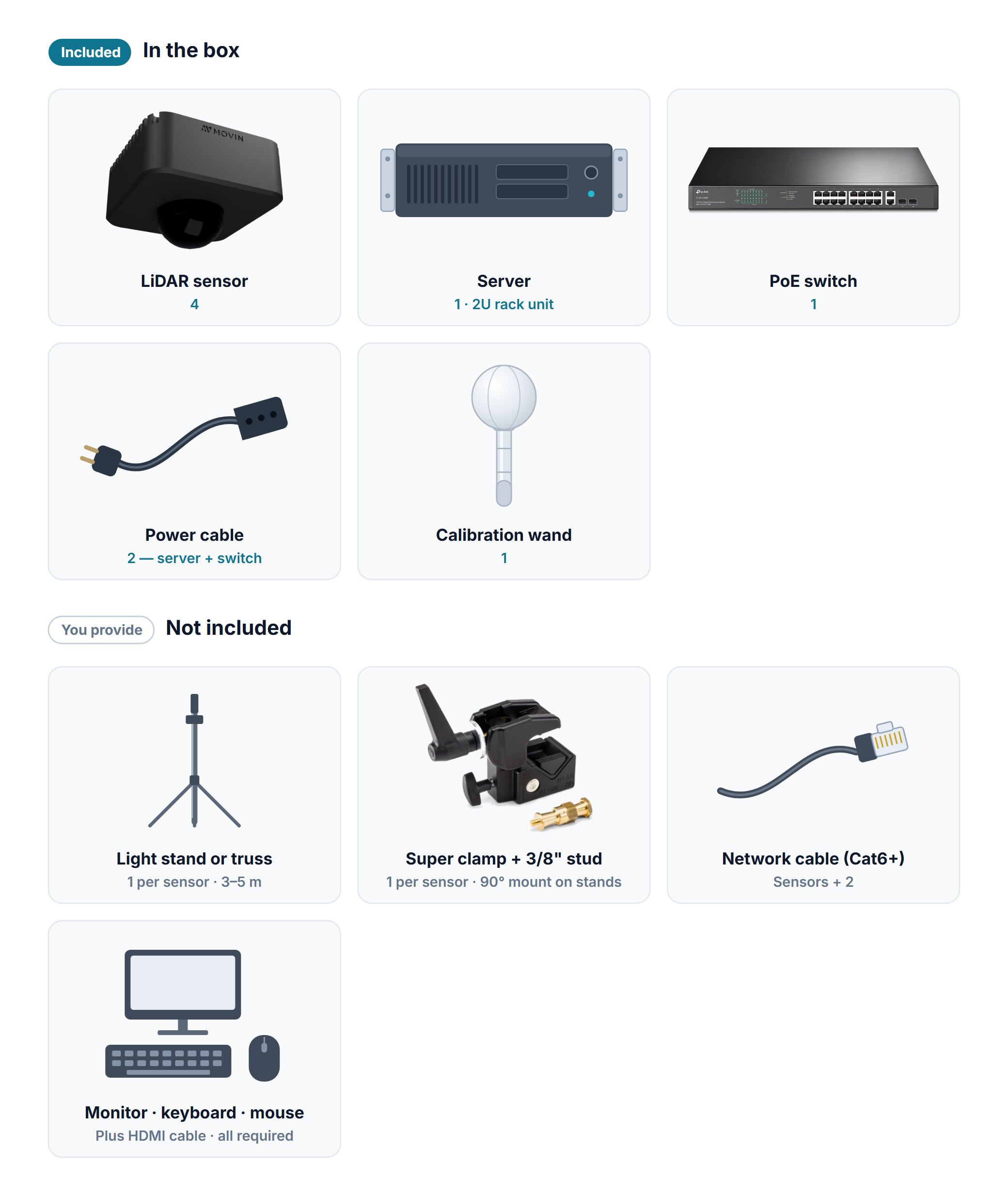
The system ships with the equipment below. Stands, clamps, and network cables differ from venue to venue, so you provide those.
## In the box
| Item | Qty | What it does |
| -------------------- | --- | --------------------------------------------------------------------------------- |
| **LiDAR sensor** | 4 | Scans the stage and builds the point cloud. |
| **Server** | 1 | A 2U rack unit. Processes the sensor data and serves the workspace screen. |
| **PoE switch** | 1 | Powers the sensors: one network cable carries both power and data to each sensor. |
| **Power cable** | 2 | One for the server, one for the PoE switch. |
| **Calibration wand** | 1 | Used in Stage 1 to align the sensors into one shared coordinate system. |
Quantities are for the standard four-sensor kit. Use your delivery list for the actual sensor count and included peripherals.
## Operator peripherals
A **monitor, HDMI cable, keyboard, and mouse** are required. You type IP addresses and filenames during setup, so the keyboard is not optional. See [Connect and power on](/movin-tracin-stage/install-the-hardware/server-back.md) for the connection and startup steps.
## Installation supplies (not included)
Per sensor you need one stand (or one spot on the truss), one clamp, one stud, and one network cable.
| Item | Qty | How to choose |
| ---------------------------------- | ------------ | ------------------------------------------------------------------------------------------------------------------------------------------------------------------------------------------------------------------------------------------------------------------------------------- |
| **Stand or truss** | 1 per sensor | A light stand that reaches 3–5 m (10–16 ft), or truss already rigged over the stage. |
| **Super clamp** | 1 per sensor | Grips a stand pole or truss pipe, and lets you angle the sensor and lock it in place. |
| **90° mount (for stands)** | 1 per stand | On a light stand the sensor can only face down if a mount or similar fitting turns the super clamp 90°. Not needed when hanging from truss. |
| **3/8 inch male stud (spigot)** | 1 per sensor | Joins the clamp to the sensor. The sensor's thread is always 3/8 inch (3/8-16) — the standard on lighting and photo stands, so the brand does not matter, but a small camera tripod's 1/4 inch thread does not fit. If your clamp's own thread is 1/4 inch, add a 1/4-to-3/8 adapter. |
| **Network cable (Cat6 or better)** | Sensors + 2 | One from each sensor to the switch, one from the switch to the server, and one from the server's OSC port to the computer running your receiving software. |
| **Cable ties** | As needed | To fix the network cable to the stand or truss. If you rig to truss and have safety cables, bring them too. |
**You configure the integration in your receiving application.** Prepare OSC UDP reception and map the point-cloud or skeleton data you need. See the [OSC message format](/movin-tracin-stage/reference/osc-format.md).
Once you have everything, go to [Mounting the sensors](/movin-tracin-stage/install-the-hardware/sensor-mounting.md).
---
# Agent Instructions
This documentation is published with GitBook. GitBook is the documentation platform designed so that both humans and AI agents can read, navigate, and reason over technical content effectively. Learn more at gitbook.com.
## Querying This Documentation
If you need additional information that is not directly available in this page, you can query the documentation by asking a question.
Perform an HTTP GET request on the following URL with the `ask` and `goal` query parameters:
```
GET https://help.movin3d.com/movin-tracin-stage/install-the-hardware/whats-included.md?ask=&goal=
```
`ask` is the immediate question: it should be specific, self-contained, and written in natural language.
`goal` is what the user is ultimately trying to achieve, the reason they need the answer. Sharing it helps GitBook give you a better, more relevant answer. A goal is most helpful when it describes the outcome the user wants rather than restating the question. For example, with `ask=how do I create an API token`, a goal like `automate deployments from our CI pipeline` lets GitBook tailor the answer to that use case.
The response will contain a direct answer to the question and relevant excerpts and sources from the documentation.
Use this mechanism when the answer is not explicitly present in the current page, you need clarification or additional context, or you want to retrieve related documentation sections.