For the complete documentation index, see llms.txt. This page is also available as Markdown.

Mounting the sensors

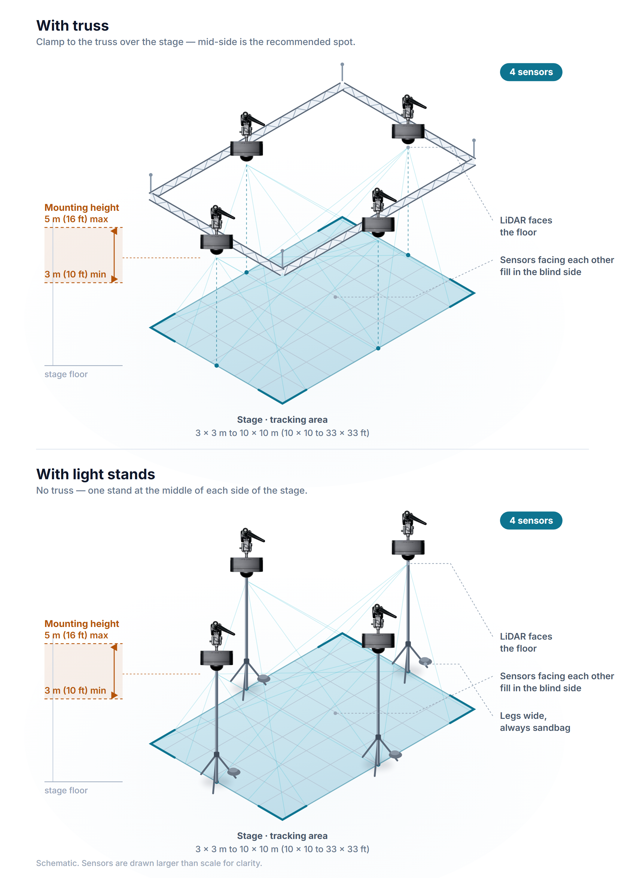
Four sensors hang high around the stage. Clamp them to the truss if there is one; otherwise put them on light stands.

Either way, mount them 3–5 m above the floor with the LiDAR facing down. See What you need for the parts list.

Sensors clamped to truss and sensors on light stands, both at a mounting height of 3 to 5 m
Top: clamped to truss. Bottom: on light stands.
Where to place them

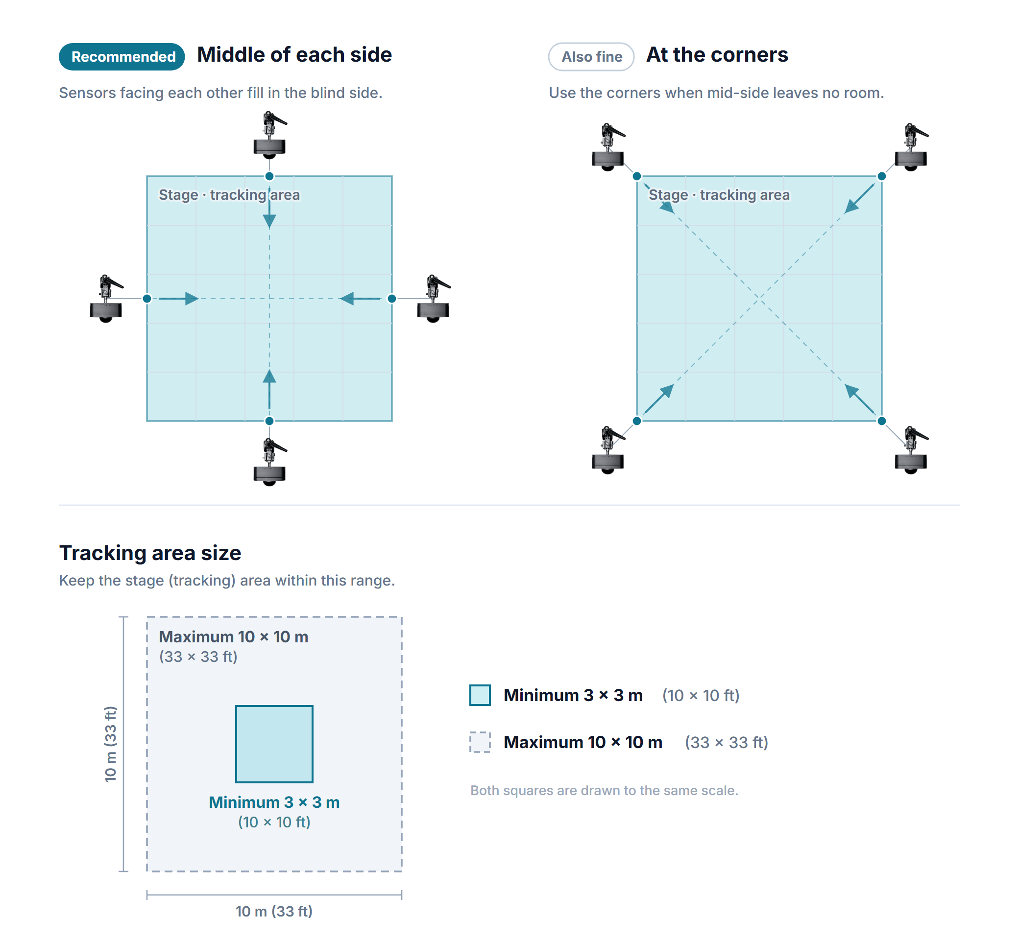
Mark out the capture area as a rectangle and put one sensor at the middle of each side, or at the four corners when that is not possible.

Sensor layout seen from above — mid-side (recommended) and corners, plus the minimum and maximum capture area
Sensor layout and capture-area limits.
  • Height3–5 m (10–16 ft) above the stage floor.

  • Overlap — neighboring sensors must see overlapping ground. During calibration the wand has to be visible to two or more sensors at once for the alignment to work.

  • Clear line of sight — keep speakers, lighting fixtures, set pieces, and drapes out of the way. Anything blocked is not captured.

How to mount

  1. Set up the stand and spread its legs wide. Skip this step when rigging to truss.

  2. Grip the super clamp onto the stand pole or truss pipe and tighten it firmly.

  3. On a stand, fit the 90° mount to the clamp so the sensor can face down. On truss the clamp is used as it is.

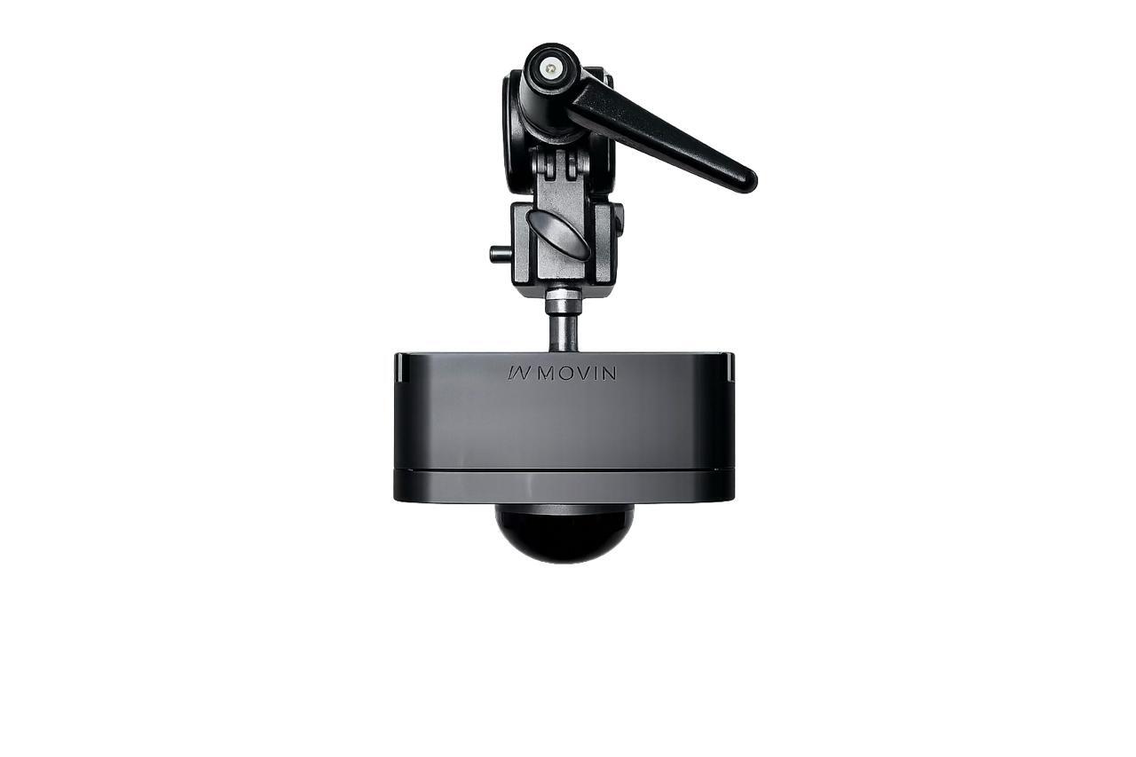
  4. Fit the stud and screw the sensor's 3/8 inch hole onto it. Check that the LiDAR faces down and sits level.

  5. Plug the network cable into the sensor, run it down along the stand, and secure it with cable ties, leaving a little slack just below the sensor.

When rigging to truss, attach a safety cable if you have one.

A LiDAR sensor held facing down on a mount by a stud
On the stud — the LiDAR faces down.
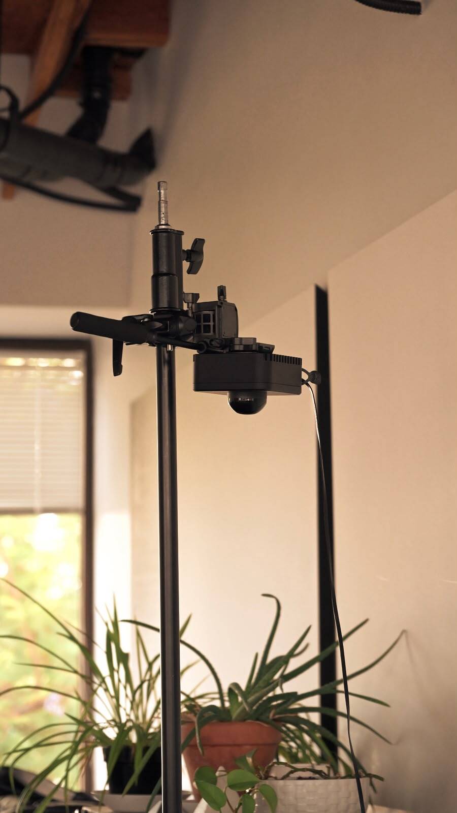
A LiDAR sensor hanging from a clamp on top of a light stand
Clamped to a light stand.

Cabling

The sensor has no power adapter. The network cable from the PoE switch carries both power and data, so the sensor turns on as soon as it is plugged into a PoE port on a powered switch. If the switch is off, the sensors are off.

Four sensor cables in the supplied switch's PoE ports
One cable per sensor into the PoE ports; the port on the right goes to the server.
  1. Run each sensor's cable down to the switch supplied with the system and plug it into any PoE port — the numbered group on the left. The PoE light for that port comes on once the sensor is powered.

  2. Join the switch to the server with one more cable: use port 17 or 18 on the right — those two do not supply power — and plug the other end into the server's LIDAR port.

Next, connect the monitor, keyboard, and mouse to the server, then power on.

Last updated